CONTACT
A producing well begins at a small, visible point: the wellhead. Beneath it, high pressures, changing temperatures, and corrosive fluids test every seal and connection. Well Head Equipment supports the casing, controls access to the well, and connects surface operations with the subsurface. Its reliability is not a minor design detail. It shapes how safely a well can be operated and maintained.
The scale of the challenge is measurable. The International Energy Agency’s Global Methane Tracker 2024 estimates that fossil fuel operations released nearly 120 million tonnes of methane in 2023. That figure does not measure wellhead failures alone, but it underscores why containment deserves serious attention. API Specification 6A sets requirements for wellhead and tree equipment, including design, materials, and testing. Stanford geophysicist Mark Zoback’s work on well integrity offers a useful principle: barriers must remain dependable throughout a well’s life. That is a paraphrase of his broader work, not a direct quotation.
Small parts. Serious consequences. Yet equipment alone cannot guarantee integrity. Installation quality, inspection, maintenance, and operating decisions matter too—and real sites rarely match a neat diagram perfectly. This guide explains what wellhead equipment does, which components matter, and how sound selection and maintenance support safer, more reliable oil and gas operations.
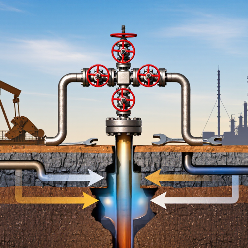
A wellhead is the pressure-containing assembly installed at the top of a well. It connects and supports the casing strings that extend downhole. Inside it, seals isolate spaces between those pipes, while a tubing hanger suspends the production tubing. During drilling, a blowout preventer connects above the wellhead; during production, a valve assembly called the tree occupies that position. The wellhead is the interface between the well and surface operations. It is not the downhole reservoir equipment.
Its parts must match expected pressure, temperature, and fluid conditions. API Specification 6A lists working-pressure ratings from 2,000 to 20,000 psi for wellhead and tree equipment. That range helps engineers specify equipment for different well conditions; it does not mean every well needs the highest rating. The casing head, spool, seals, and connectors form a physical stack, often crowded by piping and access platforms. On drawings, the boundaries look tidy. On site, corrosion, vibration, and limited clearance can complicate inspection, so equipment selection and maintenance records matter.
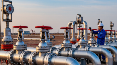
A wellhead system is more than a stack of steel. Its casing head supports the casing strings and provides a sealed connection at the surface. Casing spools add outlets for monitoring or managing pressure between strings. Above them, the tubing head supports the production tubing and seals the annular space. Small parts matter. Hangers, seals, and connections must match the well’s pressure, temperature, and fluid conditions. API Specification 6A lists rated working-pressure classes from 2,000 to 20,000 psi; this range is a design reference, not a rating that fits every well.
The Christmas tree sits above the tubing head. Its master and wing valves control flow, while a choke can regulate production pressure and rate. A reliable layout also allows technicians to isolate sections for inspection or maintenance.
The International Association of Oil & Gas Producers’ report, Process Safety Events—2019 Data, tracks process-safety events by severity, reinforcing why containment and clear isolation points deserve careful attention. A report cannot predict how one well will behave, though.
In practice, corrosion, vibration, and imperfect installation can undermine even correctly specified equipment. A tidy drawing may conceal a poor seal. Inspection records and pressure tests help verify the assembled system, but they do not replace sound engineering judgment.
Sources: API Specification 6A; IOGP Process Safety Events—2019 Data.
Wellhead equipment forms the pressure barrier between the well and surface operations. Its casing and tubing connections support the well, while seals help contain fluids under pressure. At the surface, valves provide controlled paths for starting, stopping, or isolating flow. Pressure is unforgiving. Correctly rated components and sound connections matter.
The wellhead tree uses valves to direct production and shut in the well when needed. A choke adjusts the flow opening, helping manage production rates and pressure changes downstream. Gauges give operators readings that support careful decisions, but readings need context. A sudden pressure change may signal a changing well condition, a faulty instrument, or a leak. Not every issue is obvious at first. Regular inspection, correct operating procedures, and clear records help teams identify problems before they grow.
Tips: Check gauges for unusual changes, inspect seals and connections for leaks, and confirm valves move as intended. Never treat one reading as the whole story; compare it with operating history and other measurements.
Why Is Wellhead Equipment Essential for Oil and Gas?
Wellhead Equipment Matters for Safety and Production
Wellhead equipment forms the pressure-control interface between a well and surface operations. Casing heads support casing strings, while tubing heads and valves help contain pressure and direct production. Seals, connections, and pressure-monitoring points must work together. A small leak at a connection can become a serious operational warning.
The safety margin is tangible. API Specification 6A defines working-pressure classes from 2,000 to 20,000 psi, helping operators select equipment for well conditions. But a rating alone is not a safety plan. Correct installation, compatible components, inspection, and maintenance matter just as much. Corrosion, vibration, or changing pressure can weaken a sound-looking assembly and interrupt production. Even experienced teams can miss early signs; that deserves honest review.
Tips: Check pressure ratings against the well design, inspect seals and connections for leaks, and record pressure changes. Follow the equipment maker’s procedures and applicable industry standards. If readings shift unexpectedly, pause and investigate rather than relying on appearance.
Wellhead equipment forms the pressure-containing connection between the well and surface systems. Its selection affects safe operation, maintenance access, and future workover options. A mismatch can cause leaks, costly changes, or difficult servicing. Small details matter.
Selection starts with the well’s pressure and temperature range, fluid composition, casing program, and expected loads. Engineers also check connections, materials, corrosion risks, and compatibility with valves and monitoring equipment. Sour or corrosive fluids may require specific material controls. The final configuration should follow applicable standards and be reviewed by qualified personnel. A design can still miss practical needs, such as tool clearance or access for inspection. That deserves a second look before installation.
Tips: Keep an equipment register with serial details, inspection dates, and repair history. During scheduled checks, look for corrosion, damaged seals, loose connections, and signs of leakage. Follow approved procedures for pressure testing and servicing; never rely on appearance alone. Record findings and correct defects promptly. Keep records. Routine maintenance should reflect actual service conditions, not just a calendar reminder.
| Equipment or Decision Area | Role in Well Operations | Key Selection Considerations | Typical Inspection or Maintenance Activity | Timing and Records |
|---|---|---|---|---|
| Wellhead assembly | Supports the casing and provides a pressure-containing interface between the well and surface equipment. | Well design, casing program, maximum anticipated pressure, temperature, fluid composition, and applicable specifications. | Inspect accessible connections and seals for leaks, corrosion, damage, and abnormal movement. Confirm that pressure-containing components remain suitable for service. | Inspect during scheduled well checks and after significant operating or pressure events. Record findings and corrective actions. |
| Casing head and casing spools | Support casing strings and provide outlets or connections for annulus monitoring and pressure management. | Casing sizes and loads, connection compatibility, anticipated annulus pressures, and required outlet configuration. | Check for leakage, corrosion, damaged connections, and blocked or leaking annulus outlets. Monitor annulus pressure against the well’s established operating limits. | Monitoring frequency should follow the well integrity plan, operating conditions, and regulatory requirements. |
| Welded or flanged connections and seals | Maintain pressure integrity between wellhead components. | Matching connection type, size, pressure rating, temperature range, material compatibility, and sealing arrangement. | Check for visible leakage, corrosion, loose or damaged hardware, and deterioration. Replace seals only with compatible parts and approved procedures. | Inspect during installation, intervention, and planned maintenance; document any replacement or repair. |
| Christmas tree and valves | Control and isolate production or injection flow at the well. | Required flow path, pressure and temperature conditions, fluid properties, valve type, operating method, and emergency isolation needs. | Verify valve condition and operability, inspect for leakage, and exercise valves where the approved operating procedure permits. Confirm position indicators and controls. | Use the site maintenance schedule and risk-based inspection plan; record function tests and any operating restrictions. |
| Pressure rating and design envelope | Ensure equipment can contain expected pressures and temperatures during normal operations and credible operating events. | Select ratings from the well design basis and maximum anticipated conditions. Common API 6A pressure-rating designations include 2,000, 3,000, 5,000, 10,000, and 15,000 psi; the appropriate rating depends on the application. | Check nameplates, certificates, and configuration against approved design documents. Do not exceed the documented operating limits. | Verify before installation and after changes to the well design or equipment configuration. |
| Materials and corrosion resistance | Reduce the risk of degradation from produced fluids, injection fluids, temperature, and environmental exposure. | Assess fluid chemistry, including possible hydrogen sulfide or carbon dioxide, chloride content, erosion risk, and applicable sour-service requirements. | Look for pitting, erosion, coating damage, and corrosion around connections or exposed surfaces. Apply suitable inspection methods when indicated by the risk assessment. | Set inspection scope and intervals according to fluid conditions, degradation history, and applicable standards or regulations. |
| Pressure testing and commissioning | Confirm that new or reassembled pressure-containing equipment meets approved acceptance criteria before operation. | Use the test pressure, duration, medium, and acceptance criteria specified by the governing procedure and applicable requirements. | Conduct tests with suitable calibrated instruments and documented safety controls. Investigate leakage or pressure loss before returning equipment to service. | Perform at commissioning and after relevant repairs or interventions, as required by the approved test procedure. |
| Maintenance planning and records | Support safe operation, traceability, and timely response to equipment degradation. | Base the plan on equipment criticality, operating history, well integrity risks, manufacturer guidance, and regulatory obligations. | Maintain equipment identification, inspection results, pressure-test records, repairs, parts history, and unresolved findings. | Review records regularly and update the plan after failures, changes in service, or new integrity information. |
Note: Equipment ratings, inspection methods, and maintenance intervals must be established for the specific well and verified against the approved design, applicable standards, manufacturer guidance, and local regulations.