Why Choose Drill Collar for Oil and Gas Drilling?
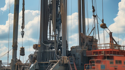
Drill Collar remains a critical component in modern oil and gas drilling, especially when wells demand controlled weight on bit and stable directional performance. The International Energy Agency’s Oil 2024 report projects global oil demand to reach about 105.4 million barrels per day by 2030. This demand will not automatically create better wells. It will require more disciplined drilling decisions, particularly in deeper, harder, and highly deviated formations.
A Drill Collar provides concentrated weight near the bit. Its stiffness also helps limit unwanted string bending, vibration, and poor hole control. The Society of Petroleum Engineers has repeatedly linked bottom-hole assembly design with rate of penetration, wellbore quality, and drilling reliability. Baker Hughes’ International Rig Count further shows the continuing scale of worldwide drilling activity, although rig numbers alone cannot measure operational difficulty. Each formation behaves differently.
That difference matters.
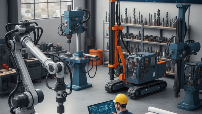
In field practice, engineers may compare collar size, connection design, metallurgy, fatigue resistance, and hydraulic behavior before selecting a bottom-hole assembly. A heavier collar is not always the better choice. Excessive weight can increase torque, connection stress, and handling demands. Insufficient weight may reduce bit stability and encourage damaging vibration. These trade-offs are easy to underestimate.
This article examines why operators choose Drill Collar, using engineering principles and established industry evidence. It also considers limitations that product brochures often simplify. Actual performance depends on depth, inclination, mud properties, bit design, and maintenance quality. The strongest selection is therefore not merely the heaviest option. It is the option supported by verified calculations, inspection records, and realistic drilling objectives.
Drill Collar Basics: 4.75–14 in OD Steel Members in the BHA
Why Choose Drill Collar for Oil and Gas Drilling?
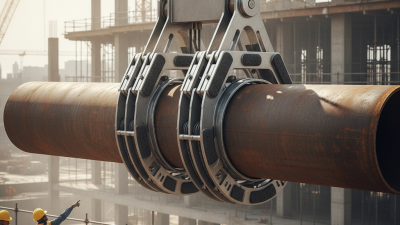
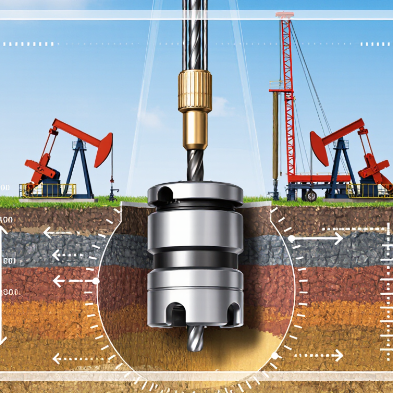
Drill collars are heavy steel members placed in the bottom-hole assembly, or BHA. Their outside diameters commonly range from 4.75 to 14 inches. This range supports different hole sizes, weight requirements, and drilling conditions. The collar applies controlled weight to the bit while keeping the lower assembly stable. Its thick wall also improves stiffness and reduces unwanted buckling. In practical field work, that stability can make surface readings easier to interpret.
A larger collar is not automatically better. Size must match the hole, bit, connections, and available lifting equipment. Engineers also consider steel grade, internal diameter, thread condition, and fatigue exposure. A damaged connection may look acceptable after cleaning. It still requires proper inspection. Small handling mistakes can become expensive downhole problems. That point is easy to underestimate.
Tips: Confirm the collar’s actual OD and length before mobilization. Check connection dimensions against the drilling program. Inspect threads, shoulders, slips, and lifting areas carefully. Record serial details and inspection results. Use suitable thread compound and calibrated torque practices. Keep collars supported on clean racks, not directly on wet ground. In my experience, a short pre-run checklist prevents more trouble than hurried repairs at the rig floor. Oversight can still happen, so review critical measurements twice.
Why Choose Drill Collar for Oil and Gas Drilling? - Drill Collar Basics: 4.75–14 in OD Steel Members in the BHA
Nominal OD
(in) |
Typical ID
(in) |
Wall Thickness
(in) |
Approx. Steel Weight
(lb/ft) |
Common Joint Length
(ft) |
Primary BHA Function |
Typical Operational Advantage |
| 4.75 |
2.25 |
1.25 |
47 |
30–31 |
Adds weight above smaller-diameter drill bits and stabilizers |
Suitable for slim-hole, workover, and directional assemblies |
| 6.50 |
2.75 |
1.88 |
93 |
30–31 |
Provides increased bit weight and stiffness |
Balances compact hole sections with useful axial loading |
| 8.00 |
3.00 |
2.50 |
147 |
30–31 |
Delivers substantial WOB while limiting drill-pipe stress |
Common choice for medium-size rotary and directional BHAs |
| 9.50 |
3.25 |
3.13 |
213 |
30–31 |
Increases BHA rigidity and resistance to bending |
Supports larger hole sizes and higher required WOB |
| 11.00 |
3.50 |
3.75 |
290 |
30–31 |
Provides high compressive capacity and strong directional control |
Effective in demanding large-hole and high-load sections |
| 12.25 |
4.00 |
4.13 |
358 |
30–31 |
Supplies very high WOB and robust BHA stiffness |
Useful for deep, large-diameter, and high-torque applications |
| 14.00 |
5.00 |
4.50 |
457 |
30–31 |
Maximizes axial load transfer and BHA rigidity |
Designed for large-hole sections where maximum structural capacity is required |
Engineering reference:
Approximate steel weight is calculated from the nominal annular area using a steel density of approximately 490 lb/ft³. Actual drill-collar dimensions, connection design, weight, and effective length vary by manufacturer, grade, machining tolerance, and drilling application. Confirm final selection against the applicable dimensional and connection specifications.
BHA Placement: Keeping the Drill String in Compression During Drilling
Drill collars give the bottom-hole assembly the stiffness needed to keep the drill string in compression. Their placement matters more than their weight alone. API Recommended Practice 7G and SPE/IADC technical guidance describe the neutral point as a critical design boundary. Above it, the drill string is mainly in tension. Below it, the assembly supplies weight on bit while resisting buckling. That margin matters.
A common field design begins with about 80% of drill-collar weight available as WOB. The remaining 20% provides a practical safety margin against shock, vibration, and changing hole conditions. This is only a starting point. Inclination, friction, mud density, stabilizer spacing, and formation strength can quickly change the load path. A collar string that looks adequate on paper may still buckle in a high-angle section. Not always.
Daily drilling reports should track WOB, torque, RPM, hookload, ROP, and vibration trends together. IADC reporting guidance supports recording these variables because isolated readings can hide developing instability. For example, rising torque with falling ROP may indicate poor BHA contact or insufficient compression control. Field engineers should also compare real-time surface data with torque-and-drag models before increasing WOB. The model is useful, but imperfect. Calibration against actual pickup, slack-off, and rotating weights remains essential. A few extra collars may improve compression, yet excessive stiffness can increase wall contact and torque. Careful BHA placement protects bit efficiency without turning the lower assembly into a rigid, unpredictable beam.
Design Options: Slick, Spiral, and Nonmagnetic Collars for Different Wells
In oil and gas drilling, a drill collar provides weight, stiffness, and directional control near the bit. Its design should match the well, not merely the rig schedule. A slick collar has a smooth outer surface and a simple profile. It offers reliable weight transfer in many vertical or gently deviated sections. Fewer external features can simplify handling and reduce spaces where cuttings collect. However, it may provide limited resistance to differential sticking. That weakness deserves attention in long, unstable intervals. Field judgment matters here.
Spiral collars include machined grooves along the body. These channels reduce contact area against the borehole wall and may lower sticking risk. They also support circulation around the collar, although results depend on mud properties and hole conditions. In sensitive formations, the groove geometry needs careful review. Nonmagnetic collars use corrosion-resistant alloys with low magnetic permeability. They help protect measurement accuracy when directional tools need a cleaner magnetic environment. Their material behavior, connection quality, and inspection records remain critical. A small alignment error can distort confidence in the survey. That part is easy to underestimate. Selection is not always perfect. Engineers should compare fatigue loads, borehole geometry, vibration, and maintenance evidence before choosing a collar style. Actual performance can challenge the original plan, so documented field feedback should influence the next run.
Selection Standards: 4145H Steel, API 7-1 Dimensions, and Fatigue Control
Why Choose Drill Collar for Oil and Gas Drilling?
Selection Standards: 4145H Steel, API 7-1 Dimensions, and Fatigue Control
A drill collar adds controlled weight near the bit and helps stabilize the bottom-hole assembly. Its thick wall resists bending under demanding drilling loads. Selection should begin with 4145H steel, a chromium-molybdenum alloy commonly chosen for strength and toughness. The purchase specification should confirm chemical composition, heat treatment, hardness, and traceable test records. Not hardness alone.
API Spec 7-1 provides dimensional and connection requirements for relevant drill stem components. Engineers should verify outside diameter, inside diameter, length, connection type, shoulder geometry, and elevator recess details. These values must match the applicable specification edition and the drilling program. Hole size, weight demand, buckling risk, and handling equipment can change the preferred collar. A drawing can look complete and still hide tolerance problems. Field decisions are rarely clean.
Fatigue control begins before the collar reaches the rig floor. Stress concentration may develop around threads, shoulders, grooves, and abrupt diameter changes. Inspectors should review surface condition and use suitable non-destructive examination methods. Make-up torque must follow the engineering procedure, not a convenient guess. Corrosion, washouts, repeated bending, and poor alignment can shorten service life. We can overtrust catalog dimensions. I would not treat one inspection report as permanent proof. Records should connect heat number, measured dimensions, inspection results, and running history. That discipline often exposes small defects before they become expensive failures.
Why Choose Drill Collar for Oil and Gas Drilling?
Selection standards: 4145H steel, API 7-1 dimensions, and fatigue control
4145H Steel
A chromium-molybdenum alloy steel commonly selected for high-strength drill-collar bodies. The “H” designation indicates controlled hardenability; final properties depend on the applicable specification and heat treatment.
API 7-1 Connection Control
Rotary-shouldered connections are selected and inspected using API 7-1 dimensional requirements. Actual body diameter, bore, connection, and tolerance must be verified against the approved drawing.
Fatigue Control
Larger wall thickness improves stiffness and bending resistance, while smooth transitions, proper make-up, inspection, and controlled dogleg severity help reduce fatigue damage.
The chart uses representative nominal drill-collar body sizes commonly manufactured for drilling applications. Connection dimensions and acceptance criteria must be confirmed from the current API 7-1 edition and the approved product drawing.