- Home
- About TKL
- Factory Tour
- Products
- Blog
- Contact Us

CONTACT
Leave Your Message
CONTACT
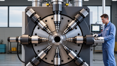
A Pipe Swaging Machine reshapes a pipe or tube end without removing large amounts of material. It can reduce, expand, taper, or form a socket for joining components. The machine applies controlled force through dies, rollers, or tooling designed for the required profile. In practical fabrication, the result may look simple: a straight tube enters, then leaves with a precise formed end.
The working principle depends on the machine design. Some models use rotary dies that strike or compress the tube rapidly. Others apply hydraulic or mechanical pressure in a single forming cycle. Operators must match the tooling to the pipe diameter, wall thickness, material, and finished shape. Steel, stainless steel, copper, and aluminum may respond differently. Small errors can cause wrinkles, cracks, ovality, or excessive thinning.
This is where reliable technical judgment matters. Experienced fabricators inspect samples, measure dimensions, and adjust force gradually rather than trusting a preset blindly. Manufacturer instructions, material data, and recognized engineering practices should guide production decisions. A common mistake is assuming every pipe can be swaged with identical settings. It cannot. Proper lubrication, alignment, guarding, and operator training also influence the final quality. The process is efficient, but not effortless. Understanding how a Pipe Swaging Machine works helps users select suitable equipment, prevent avoidable defects, and produce consistent connections. Some applications still require testing or expert review, especially when dimensional accuracy and service reliability are critical.
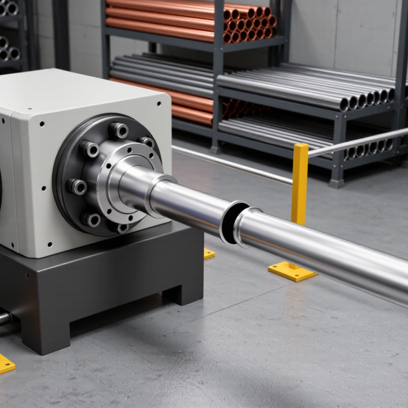
A pipe swaging machine is industrial equipment that reshapes a pipe end without cutting away its material. It reduces or expands the tube diameter in a controlled area. The process creates a tapered, stepped, or formed end for joining another component. In practical workshops, technicians use swaging when a clean and strong connection matters.
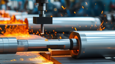
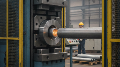
The machine holds the pipe inside a die or forming tool. Hydraulic, mechanical, or rotary force then presses the pipe against that tool. The metal flows gradually into the required shape. Some machines use several forming passes. This approach helps limit wrinkles, cracks, and uneven wall thickness. The operator checks the pipe size, material grade, wall thickness, and die condition before forming. Small errors can become expensive.
A swaging machine may include a frame, drive system, clamping unit, forming dies, and control panel. Manual models suit limited production, while automated equipment supports repeatable output. However, repeatability is not perfection. Poor alignment can leave an angled end or visible marks. Excessive force may thin the pipe locally. In my experience, careful measurement after each trial is more reliable than trusting settings alone. Heat, lubrication, and tool wear also influence the final result. The process looks simple, but judgment still matters.
| Data Dimension | Description | Key Facts |
|---|---|---|
| Definition | A pipe swaging machine is equipment used to reduce, shape, or form the end of a pipe or tube by applying controlled mechanical force. | Swaging is a metal-forming process that changes the tube profile without removing material. |
| Primary Purpose | The machine prepares pipe ends for joining, insertion, fitting, sealing, or connection to another component. | Common results include reduced ends, tapered sections, expanded ends, and formed connection profiles. |
| Basic Working Principle | The pipe is positioned in a die, collet, or tooling set. Radial or axial force is then applied to reshape the selected section. | The tooling controls the final outside diameter, inside diameter, length, and profile. |
| Typical Operating Sequence | Cut and deburr the tube, load it into the machine, align the workpiece, clamp it, perform the forming cycle, and remove the finished part. | Correct alignment and secure clamping help prevent uneven deformation and tool damage. |
| Main Forming Methods | Machines may use rotary, radial, axial, hydraulic, mechanical, or press-based forming methods. | The suitable method depends on tube material, wall thickness, geometry, production volume, and required accuracy. |
| Major Machine Components | Typical components include a frame, drive system, forming head, dies or rollers, workholding device, control panel, and safety guards. | Tooling is usually replaceable so that different pipe sizes and profiles can be processed. |
| Compatible Materials | Swaging can be performed on many ductile metals, including carbon steel, stainless steel, aluminum, copper, and selected alloys. | Material formability, hardness, wall thickness, and work-hardening behavior must be considered before processing. |
| Common Finished Profiles | Typical profiles include straight reductions, tapers, stepped sections, flared ends, beaded ends, and socket or insertion sections. | The achievable profile is determined by the die shape and the machine’s forming capacity. |
| Dimensional Control | Finished dimensions are checked using tools such as calipers, micrometers, gauges, templates, or coordinate-measuring equipment. | Actual tolerances depend on the machine, tooling, material, process settings, and inspection method. |
| Advantages | The process can produce consistent pipe-end geometries with little or no material waste. | It can reduce secondary machining, support repeatable production, and preserve the continuity of the tube material. |
| Typical Applications | Applications include exhaust assemblies, fluid lines, heat exchangers, structural tubing, furniture components, and general fabricated pipework. | The required pipe profile varies according to the joining, sealing, or assembly method used. |
| Quality Risks | Possible defects include wrinkling, cracking, excessive thinning, ovality, inaccurate dimensions, surface marks, and misalignment. | Proper tooling selection, lubrication where appropriate, controlled force, and gradual forming can reduce defect risks. |
| Safety Requirements | Operators should use guarding, emergency stops, suitable personal protective equipment, and approved loading and unloading procedures. | Hands must be kept away from moving dies, rollers, clamps, and pinch points during operation. |
| Selection Factors | Important factors include pipe diameter, wall thickness, material, required profile, production rate, dimensional tolerance, automation level, and available tooling. | Machine capacity should be matched to the complete forming requirement rather than pipe diameter alone. |